- The non-frick cylinder has been changed from October 1, 2023.
The lineup is shown in the table below.
| Cylinder diameter | stroke | ||||||||||
| 20 | 50 | 75 | 100 | 125 | 150 | 175 | 200 | - | - | - | - |
| 30 | 50 | 75 | 100 | 125 | 150 | 175 | 200 | 250 | 300 | - | - |
| 40 | - | - | 100 | 125 | 150 | 175 | 200 | 250 | 300 | 350 | 400 |
| 50 | - | - | 100 | 125 | 150 | 175 | 200 | 250 | 300 | 350 | 400 |
| 63 | - | - | 100 | 125 | 150 | 175 | 200 | 250 | 300 | 350 | 400 |
| 80 | - | - | 100 | 125 | 150 | 175 | 200 | 250 | 300 | 350 | 400 |
| 100 | - | - | 100 | 125 | 150 | 175 | 200 | 250 | 300 | 350 | 400 |
Please check the new drawings below.
新型NFC図面20,30,40,50.pdf
新型NFC図面63,80,100.pdf
Some dimensions have been changed from the old model.
NFC寸法変更部一覧20,30,40,50.pdf
NFC寸法変更部一覧63,80,100.pdf
Purpose of use
- The main purpose of this device to provide low-friction and low-hysteresis (low mechanical loss) during reciprocating motion.
Special features
- 1. Low mechanical loss and hysteresis.
- 2. Long stroke production.
- 3. Low maintenance.
- 4. Simplified structure compared with conventional products prevents failure due to rubber getting caught. The sliding part of the cylinder is lubricated by the by an air film through micro-leakage, low sliding drastically reduces wear.
- 5. Operated by micro-pressure.
- 6. Long life.
- 7. Operating cylinder is very light, made from CFRP (Carbon Fiber Reinforced Plastic).
Specification
-
Cylinder bore diameter φ20~φ100 Operating pressure range 0.01〜0.3MPa Temperature / Humidity 20℃〜25℃ / Under 50%RH Lubricant / Moisture Unavailable Initial pressure 0.16kPa for NFAC-40-100 Working pressure 1kPa for NFAC-40-100
Use
- ● Reeling machine touch roll
- ● Dancer control device for web transport line
Production range
- ● Cylinder diameter is Φ20〜Φ100(Standard)
- ● Other sizes are also available (Custom-made)
Distribution agent
- ● Exclusive agent for Non Fric Cylinder
- SHINKO Corp TEL:81-6-6552-3171
- ● Please contact the above number for estimates / quotations.
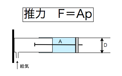
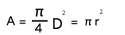
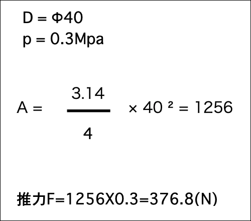
Thrust calculation
↑ Intake
|
|
Commentary
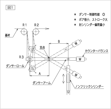
- ● Image 1 is an example of vertical dancer where the distance from Non Fric Cylinder (below NFAC) support point and that to the shaft of the dancer roll around the fulcrum A and B are equal in length. In this case, the thrust applied by NFAC is equal to that of the dancer roll and transport is accompanied by a change in direction.
- ● For example, if NFAC thrust is set to 50N, the dancer roll thrust will receive -50Nga.
- ● Since the reel angle of substrate is set to 180 degrees, NFAC thrust is halved between dancer roll’s downstream and upstream, the resulting 25N tension matches that of NFAC thrusts. In this use case, if the film tension for some reason changes, the dancer roll will move either up or down. The amount is transmitted to NFAC via dancer arm fulcrum, pushing or pulling the cylinder, consequently changing the pressure inside NFAC.
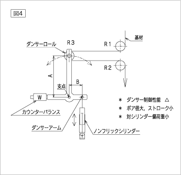
- ● Typically, the NFAC vent is equipped with an electro-pneumatic converter and high precision pressure regulator valve, allowing for NFAC to regulate internal pressure automatically by reducing or increasing the amount of air. However, as can be seen in Image 4, when the proportion of the distance to dancer roll shaft and that to NFAC fulcrum is skewed, wider movements by the dancer roll can result in dancer arm deformation, NFAC mechanical loss and bearing friction which all together can lead to the movement of the dancer around its center to become one sided, leading to a loss of functionality.
- In order to prevent that, please avoid the method demonstrated in Image 4.
- Also, when using an NFAC dancer please limit the number to one cylinder.
- Using two cylinders may result in interference and malfunction.
|
図1 |
図2 |
図3 |
図4 |
Caution
- Use a long stroke as much as possible.
- Usable temperature is normally 25℃. Please contact us if exceeded.
- Zero temperature coefficient of CFRP (Carbon Fiber Reinforced Plastics) is used for the outer cylinder and, because the inner cylinder is made from aluminum which is susceptible to temperature expansion, the gap between the inner and outer cylinders may shrink resulting in the two coming into contact and halting.
- This can also lead to a change in the amount of leakage.
| How to use |
Only vertical |
| Accumulator |
Even if the load (air demand of the cylinder) varies, it is important for accumulator to be set so that air supply source does not change. One recommendation is to use a container that can bear the pressure of 0.5Mpa, In this case, please be vigilant of rusting that may damage the cylinder. (A mist separator is recommended for use.) |
| Piping | Regarding the air pipes on the side receiving the load from the accumulator, the thicker and shorter the better. |
| Air regulator |
Please make sure to insert the air regulator right before the cylinder. (Precision regulator) |
| Dancing direction |
Vertical dancer is recommended to be used as dancer device. |
| Compressed Air |
Please use oil-free purified air and a dust filter. |
| Offset Load |
Unavailable. |
| Guide Roll |
Please use a dancer roll which rotates lightly. |
| Air supply | When air supply runs short even for a short time, the cylinder thrust declines. |
- For use in configurations other than vertical, please refer to Linear guide air cylinder.
管理者の許諾を得ずに、当サイト内のあらゆる画像や文章をなどの情報を無断転載することは、著作権侵害にあたる行為のため禁止します
